This is an old revision of the document!
Please contact support@seedrobotics.com for more information on this interface.
Connection Diagrams and Connector Pinouts
Main Connector: RS485 interface
The main connector is located at the back of the unit (it's a 3 or 4 in connector). It is the via through which you command and control your unit and is the most important connection for power and control.
This page details the high level connection diagrams for the most common types of interfaces.
At the bottom of the page we list the exact pinout so that you ca also build your own cable or interface, if you so desire.
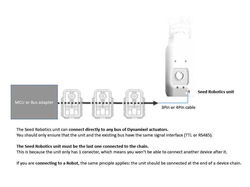
The RS485 interface uses a differential pair to operate in half duplex mode. In this mode operation on a daisy chained environment is possible.
Seed Robotics PDC Interface and Supplied Power Adapter

Seed Robotis PC Interface Board + Power Interface Board:
(Using Robotis SMPS2Dynamixel + USB2Dynamixel or U2D2)

Connecting to an existing Dynamixel Servo Chain or Dynamixel based Robot:
Connect to a generic RS485 converter:
The diagram below is generic: it is designed in a way to suit all major RS485 converters.
If you have any question regarding connection to your specific converter, please contact support@seedrobotics.com and we'll be happy to assist you.
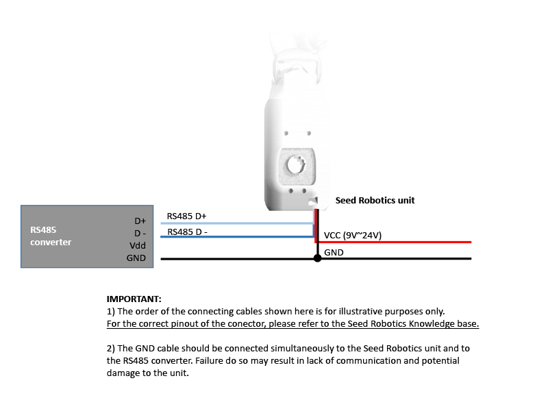
Connector pinout for RS485 signal level interface:

Please note:
- Acceptable voltage range is typically 9V~24V. Please refer to the documentation of your specific model for the exact voltage range accepted.
- The GND signal MUST always be connected to the RS485 converter; failure to do so may result in damage to the unit (or at least communication failures)
- When selecting an RS485 converter, please observe the maximum baud rate of the converter. Bear in mind the default communication speed on the main port is 1Mbps. (it can be reduced by user setting but performance is degraded)
Connection Diagrams and Connector Pinouts
Main Connector: One wire TTL interface
The main connector is located at the back of the unit (it's a 3 or 4 in connector). It is the via through which you command and control your unit and is the most important connection for power and control.
This page details the high level connection diagrams for the most common types of interfaces.
At the bottom of the page we list the exact pinout so that you ca also build your own cable or interface, if you so desire.
The One Wire TTL interface uses a differential pair to operate in half duplex mode. In this mode operation on a daisy chained environment is possible.
Seed Robotics PDC Interface and supplied Power Adapter
Seed Robotis PC Interface Board + Power Interface Board:
(Using Robotis SMPS2Dynamixel + USB2Dynamixel or U2D2)

Xevel Labs USB2AX:

Connect to an existing Dynamixel Servo Chain or Dynamixel based Robot:
Connector pinout for One Wire TTL UART signal level interface:

Please note:
- DATA is a bi-directional UART signal used for communication. It operates in the 3.3V - 5V voltage range. Your MCU must normally be in RX mode and change to TX mode when it needs to transmit data. A Tri state buffer can be used to achieve this functionality.
- Acceptable voltage range is typically 9V~24V. Please refer to the documentation of your specific model for the exact voltage range accepted.
- The GND signal MUST always be connected to the RS485 converter; failure to do so may result in damage to the unit (or at least communication failures)
- When selecting a converter, please observe the maximum baud rate of the converter. Bear in mind the default communication speed on the main port is 1Mbps. (it can be reduced by user setting but performance is degraded)
Connection Diagrams and Connector Pinouts
All Seed Robotics models come standard with USB interface and one main interface (the main connector), with a logical interface (by default this is RS485; users can also request One Wire TTL or Full Duplex TTL ).
Previously an Optional Bluetooth Module could also be installed on the unit and connects to any terminal that supports the Bluetooth SPP (Serial Port) Profile.
Below we detail the connector types for the units and connection diagrams with the most commonly used tools.
Supplying Power
External power must always be supplied through the main connector port (the one with the 3 pin or 4 pin connector on the back of the unit).
If you intend on using other interfaces for control such as USB or Bluetooth, power must still be applied through this connector on the VDD and GND pins.
Acceptable voltage range is typically 9V~24V. Please refer to the documentation of your specific model for the exact voltage range accepted.
Main Connector
The main connector is located at the back of the unit (it's a 3 or 4 in connector). It is the via through which you command and control your unit and is the most important connection for power and control.
(connecting via USB or other means is optional, and usually intended for Diagnostics and maintenance; regular operation and control is done via this Main Connector).
Please select the type of interface in your main connector (this should be shown in our Quotation; by defaut it is RS485)
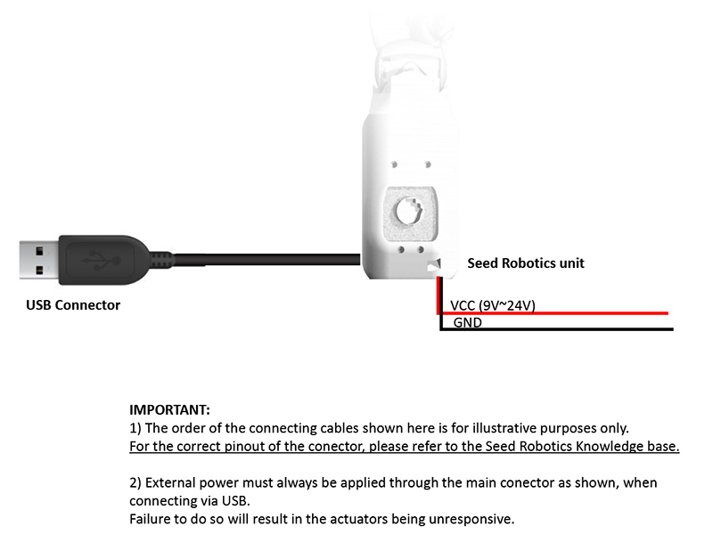
Connecting via USB
The USB connector is available on the side of the unit (a small cover may need to be removed to access it).
This connector is a standard micro-USB type connector. Once connected to the host, it will create a Virtual Serial Port.
When connecting via USB, you must still apply power through the Main Connector as shown in the diagram below. Failure to do so will result in the Actuators not responding and the hand not moving as they will not be powered.
As an alternative, you can apply External Power by simply connecting the normal Main Connector (i.e. if you have PC Interface Cable set from Seed Robotics (or something similar) to control your unit, simply connect it, and apply power as usual)
For more information, see the EROS: Setting up the USB Connection documentation.
Connecting via Bluetooth
The Bluetooth interface is an option that can be installed on your unit, at the time you place your order.
The Bluetooth interface uses the Bluetooth Serial Port Profile (SPP) to create a Virtual Serial port on the remote host.
IMPORTANT: you can connect via Bluetooth even if your unit is already connected via any of the other ways shown above. The unit can simultaneously accept commands through the main port and the Bluetooth interface.
This is especially convenient for online, wireless diagnostics and maintenance.
When connecting via Bluetooth, you must apply power through the Main Connector as shown in the diagram below.
Failure to do so will result in the Actuators not responding and the hand not moving as they will not be powered.

By default the firmware is configured to expose the Console over Bluetooth. This means that control using the Dynamixel protocol is not enabled by default on the Bluetooth port (although it can be enabled if required).
For more information, see Using the Bluetooth Interface Module.
Copyright © 2015-2023 Seed Robotics Ltd