Connection Diagrams and Connector Pinouts
Main Connector: RS485 interface
The main connector is located at the back of the unit (it's a 3 or 4 in connector). It is the via through which you command and control your unit and is the most important connection for power and control.
This page details the high level connection diagrams for the most common types of interfaces.
At the bottom of the page we list the exact pinout so that you ca also build your own cable or interface, if you so desire.
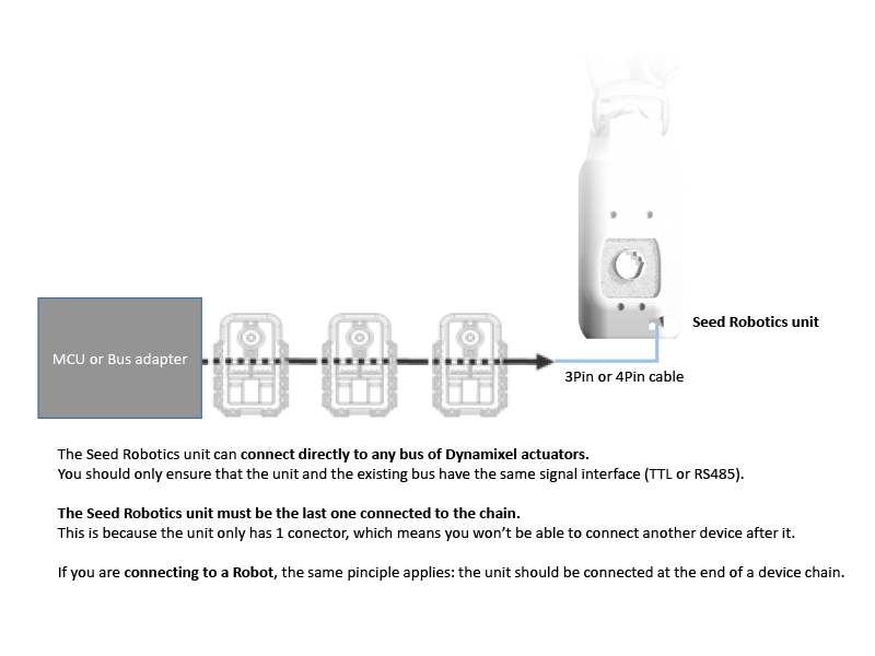
The RS485 interface uses a differential pair to operate in half duplex mode. In this mode operation on a daisy chained environment is possible.
Seed Robotics PDC Interface and Supplied Power Adapter

Seed Robotis PC Interface Board + Power Interface Board:
(Using Robotis SMPS2Dynamixel + USB2Dynamixel or U2D2)

Connecting to an existing Dynamixel Servo Chain or Dynamixel based Robot:
Connect to a generic RS485 converter:
The diagram below is generic: it is designed in a way to suit all major RS485 converters.
If you have any question regarding connection to your specific converter, please contact support@seedrobotics.com and we'll be happy to assist you.
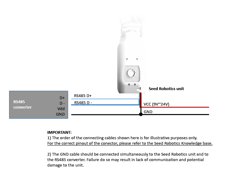
Connector pinout for RS485 signal level interface:

Please note:
- Acceptable voltage range is typically 9V~24V. Please refer to the documentation of your specific model for the exact voltage range accepted.
- The GND signal MUST always be connected to the RS485 converter; failure to do so may result in damage to the unit (or at least communication failures)
- When selecting an RS485 converter, please observe the maximum baud rate of the converter. Bear in mind the default communication speed on the main port is 1Mbps. (it can be reduced by user setting but performance is degraded)
Copyright © 2015-2023 Seed Robotics Ltd