SR-RH4D: Unpacking and Mechanical Assembly
Congratulations on your purchase of the SR-DH4D Hand. This hand is the result of years' experience in hand design and use and it aims at incorporating everything a robot builder needs: reliability^3, ease of use and compatibility with existing robot platforms in both hardware and software.
Package Contents
When unpacking, please check your package contents. The set of spares varies depending on whether your purchased a single hand or a pair.
For a single hand
- 1x SR-RH4D Hands
For a Pair of Hands
- 2x SR-RH4D Hands
Note: The Bluetooth interface and Capacitive Pads, if ordered, are installed inside the unit. They will not be visible from the outside.
If your ordered the PC Interface Board + Power and Data Hub + Power Supply
- 1x Power Supply 12V
- 1x USB to Serial converter cable. \\Typically, this will be a special 2-in-1 cable with miniaturized circuitry built inside the USB connector.
- 1x Power and Data Hub board
- 1x or 2x Long connection cable (depending on whether you ordered one unit or a pair or units)
- 2x Short connection cables
The Long and Short connection cables are similar and can be interchanged if the user needs. The Long cable is usually used to connect to the main unit but this is not mandatory; any of the cables can be used.
Assembling the unit on your Robot: Overview
The hand is assembled by means of 4-6 screws located on the back (“wrist”) position. These screws are designed with common spacing in mind, being compatible with assembly on Darwin-OP/Robotis OP2 (for OP assembly instructions, see below).

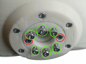
Assembly screws are already pre-assembled (in green). Remove them, including the washers. Pay attention to NOT remove the screws in red or any other screws and they are structural to the hand assembly.
To prepare assembly, align parts as seen in the next picture (palm facing down and bracket sides pointing up).

The wrist rotation has slightly under 180º of range. Therefore, for correct assembly, rotate central hub in the direction marked in the picture according to the side on which you are assembling: left hand or right hand. ( To rotate the central hub you can use one of the hex keys inserted in the central screws. )
The suggested mounting position assumes an application focusing on grabbing objects underneath the hand. However if your application requires a different range of motion, you may adjust the mounting position according to your needs, bearing in mind the range of motion of the wrist.
If you are Assembling on Darwin-OP / Robotis OP2, the assembly screws are to be assembled through the holes marked in blue. (the frame shown is from the OP robot).
Re-fit the included screws and connect the cable from the Hand to the Robot.
Specific instructions for the Darwin-OP/Robotis OP2 Robot
If you are assembling on a Darwin/Robotis OP[2] robot, you can find detailed instructions below on how to go from the standard configuration to the installed hands.
To assemble on Darwin/Robotis OP[2], start by removing all the screws securing the elbow bracket to the forearm bracket. Notice orientation of aligning mark on servo horn.

Remove all screws attaching elbow bracket to forearm bracket. Suggestion: make sure you do not lose these screws by re attaching them to forearm bracket.
Now follow the instructions in the Overview Section, to align the Hand unit with the OP2 bracket:
The wrist rotation has slightly under 180º of range. Therefore, for correct assembly, rotate central hub in the direction marked in the picture according to the side on which you are assembling: left hand or right hand.
( To rotate the central hub you can use one of the hex keys inserted in the central screws. )
The suggested mounting position assumes an application focusing on grabbing objects underneath the hand. However if your application requires a different range of motion, you may adjust the mounting position according to your needs, bearing in mind the range of motion of the wrist.
The assembly screws are to be assembled through the holes marked in blue.
Overlap servo bracket with gripper so that central screws are located under green circles for right hand or red circles for left hand. (again this assumes assumes an application focusing on grabbing objects underneath the hand. However if your application requires a different range of motion, you may adjust the mounting position according to your needs, bearing in mind the range of motion of the wrist. )

Attach two screws in opposing positions to secure gripper to bracket. IMPORTANT: When tightening screws do not push them in. Screws should be tightened by rotation only.
At this point it is strongly recommended that you test the range of rotation of the gripper by turning them manually or ideally by turning them on and try to move them in software.
If you are satisfied with range of movement secure remaining screws. If adjustment is needed remove the two pilot screws, rotate gripper to next available position and re-attach screws.
BEST PRACTICE: we suggest applying thread lock glue (included in your Darwin/Robotis OP[2] kit) to the screws holding the hand.
Reassemble elbow bracket in robot, taking note of alignment marks on servo horn to ensure proper orientation.
Complete the assembly by connecting a Dynamixel cable from the hand to the nearest servo.
Copyright © 2015-2023 Seed Robotics Ltd